How To Install The Atwood Air Command Rooftop RV A/C With Heat Pump
Question:
WE ARE DESIGNING A CUSTOM SERVICE BODY FOR A CUSTOMER WHO WOULD LIKE TO MOUNT AN AT15033-22 UNIT ON THE ROOF. WE WOULD LIKE TO SEE AN INSTALLATION MANUAL AND INSTRUCTION FOR INSTALLING THIS UNIT. WE NEED TO UNDERSTAND HOW THIS UNIT MOUNTS AND WHAT SIZE CUTOUTS AND MOUNTING HOLES ARE NECESSARY, SO WE CAN DESIGN OUR ROOF TO SUPPORT IT. PLEASE LET ME KNOW ASAP AS THIS PROJECT IS TIME SENSATIVE.
asked by: JOHN G
Expert Reply:
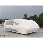
We do not have an installation video out yet for the Atwood Air Command Rooftop RV Air Conditioner w/ Heat Pump # AT15028-22, however I would be happy to walk you through the installation process.
To begin disconnect all the power to the unit before installation. Not doing so could result in serious injury.
This installation begins with the ceiling template.
You'll need to:
1. Hold the Ceiling Template up to the roof opening, and make sure the large plate faces the rear of the RV.
2. Start each mounting bolt through the Ceiling Template and up into the unit base pan by hand.
3. Evenly tighten all four mounting bolts. Do not exceed 4.4 ft-lbf (6 Nm).
Next we will move to installing the divider plate.
1. Measure the ceiling-to-roof thickness.
– If the distance is 2.0 in. to 3.75 in. (50 mm to 95
mm), remove the perforated tabs from the Divider
Plate.
– If the distance is 3.75 in. to 5.5 in. (95 mm to
140 mm), do not remove the perforated tabs from
the Divider Plate.
2. Remove the backing paper from the double-sided tape located on the Ceiling Template.
3. Firmly push the Divider Plate up to the bottom of the unit base pan. The foam tape on the Divider Plate must seal to the bottom of the Base Pan.
4. Slightly push the Divider Plate against the double-sided tape on the Ceiling Template.
5. Remove the backing paper from the 0.12 in. x 7 in. x 18 in. (3 mm x 178 mm x 457 mm) self-adhesive insulation and stick it onto the Ceiling Template Divider Plate.
Also, Excess width is intended to seal the Divider Plate to the sides of the roof opening. This is to help prevent cold air discharge from circulation into the unit’s return air opening.
Finally we will be installing the Return air cover, and the conversion template kit.
1. Remove the Filter Frame (with Filter) from the Return Air Cover.
2. Remove the Vent Cover from the Return Air Cover.
3. Cut the Foam from the kit to 16.75 in. (425.45 mm) and place it onto the Foam Barrier on the Return Air
Cover.
4. Place the Conversion Template above the Return Air Cover with the side of the double-sided tape facing
the roof of the RV.
5. Align the Conversion Template and the Return Air Cover.
6. Peel off a small amount of the backing on the double-sided tape.
7. Remove the rest of the backing on the double-sided tape.
8. Secure the Conversion Template and the Return Air Cover Assembly to the Ceiling Template using the
four provided #2 Square Drive Screws.
9. Slide the Vent Cover and the Framed Filter fully into the Return Air Cover Assembly.
The only thing left to do is to make sure all the electrical connections are good to go, restore power to the unit and check for functionality.


(click to enlarge)

(click to enlarge)

(click to enlarge)

(click to enlarge)

(click to enlarge)

(click to enlarge)